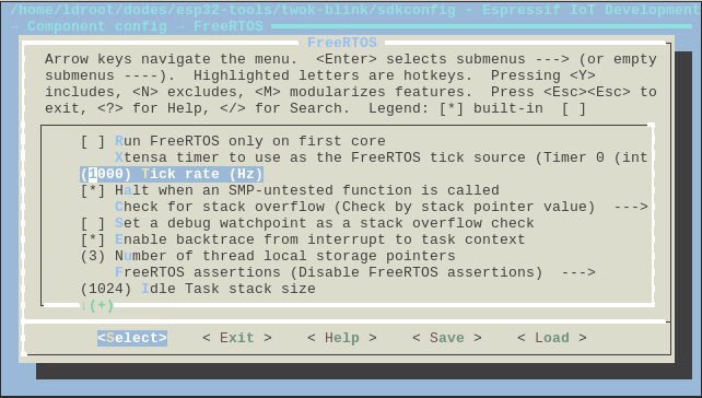
You know that the maximal tick rate in ESP-IDF is 1000Hz.

This is ok for almost applications and if you require sub-milli time precision, the extra timer or interrupt would be your friend.
But why can't be 2000Hz tick rate set on 240Mz CPU?
Here is a famous LED blinker example with 500Hz blinks:
void app_main()
{
  gpio_set_direction(GPIO_NUM_2, GPIO_MODE_OUTPUT);
  int level = 0;
  while (true) {
    gpio_set_level(GPIO_NUM_2, level);
    level = !level;
    vTaskDelay(1 / portTICK_PERIOD_MS);
  }
}
.
If you like 1kHz blinks, you need 0.5ms delay instead of 1ms delay.
Here is a hack for this.
diff --git a/components/freertos/include/freertos/xtensa_timer.h b/components/freertos/include/freertos/xtensa_timer.h
index 9bb8648..5c810a3 100644
--- a/components/freertos/include/freertos/xtensa_timer.h
+++ b/components/freertos/include/freertos/xtensa_timer.h
@@ -147,7 +147,7 @@ editing this here or in xtensa_rtos.h, or compiling with xt-xcc option
Derivation of clock divisor for timer tick and interrupt (one per tick).
*/
#ifdef XT_CLOCK_FREQ
-#define XT_TICK_DIVISOR     (XT_CLOCK_FREQ / XT_TICK_PER_SEC)
+#define XT_TICK_DIVISOR     (XT_CLOCK_FREQ / XT_TICK_PER_SEC / 2)
#endif

#ifndef __ASSEMBLER__
.
i.e. fakes 120MHz CPU for freertos :-)
It gives 1000Hz square wave on GPIO2 for the above blinker code snippet:

All my more complex applications have worked without problem on this hack. Looks ESP-IDF system itself doesn't depend on port tick constraints. It's expected and fine.
I don't think this hack is the right thing to do. Last resort, though.
Happy Hacking!